Copyright © 2026 K.G.Matzen. Powered by iglobalwin.com
Design Requirements for Secondary Sedimentation Tanks
2025-06-24
Common types of secondary clarifiers include horizontal flow, radial flow, and inclined plate/tube sedimentation tanks.
1. Horizontal Flow Sedimentation Tank
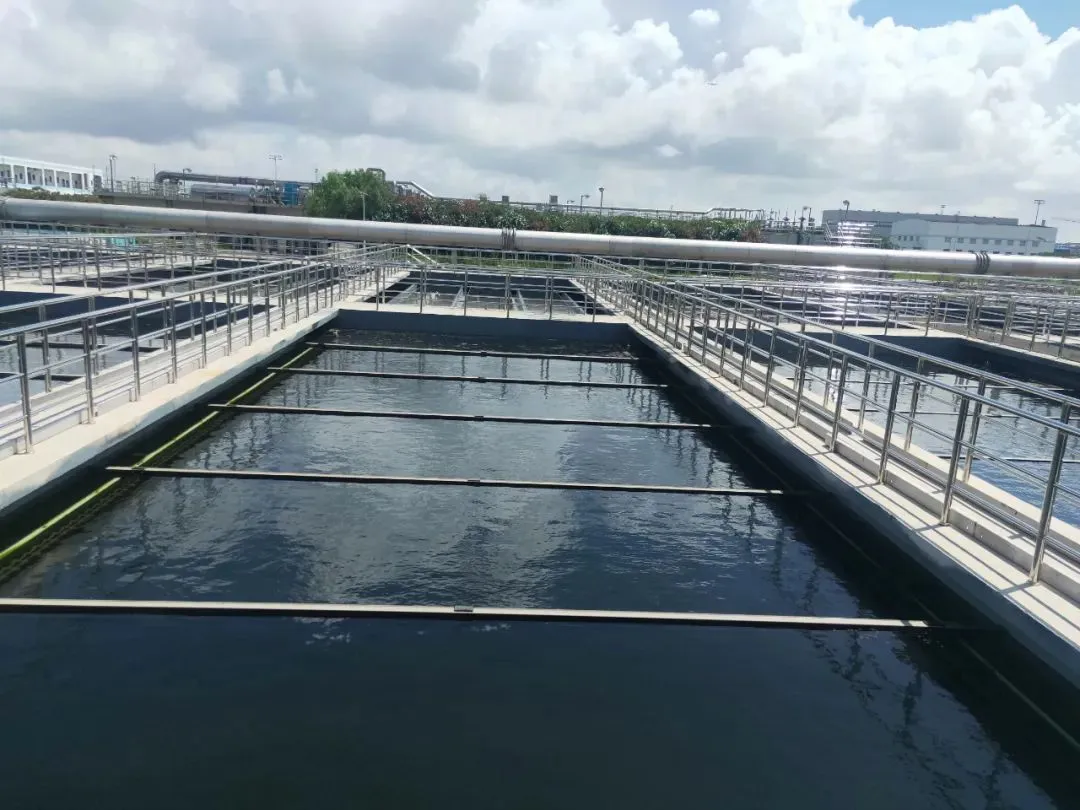
Horizontal flow tanks are typically rectangular. Water enters through an inlet zone where flow is dissipated and equalized, then moves slowly in a horizontal direction through the sedimentation zone. Suspended solids settle to the bottom, while clarified water exits over weirs and is discharged through an outlet channel.
Basic Design Requirements:
Length: typically 30~50 m (not exceeding 60 m)
Width: typically 5~10 m
Effective depth: generally 2.5~3.0 m (not exceeding 3 m)
Length-to-width ratio ≥ 4: 1; length-to-depth ratio between 8~12
a. Sludge Collection: When mechanical sludge scrapers are used, sludge hoppers are installed at the inlet end. Tank bottom slope towards the sludge hopper should be ≥ 0.01 (usually 0.01~0.02). Scraper travel speed should not exceed 1.2 m/min (typically 0.3~0.9 m/min).
b. Hydraulic Loading: As a primary clarifier: surface loading rate = 1~4.5 m³/(m²·h), max horizontal velocity = 7 mm/s
As a secondary clarifier: surface loading rate ≤ 1 m³/(m²·h), max horizontal velocity = 5 mm/s.
c. Inlet Design: Must include flow-straightening devices. Common configurations include: Overflow weir + perforated baffle;Bottom inlet + baffle;Submerged inlet + baffle;Submerged inlet + perforated baffle.For perforated baffles: open area 6%~20% of cross-section; velocity through holes = 0.08~0.1 m/s; openings should be tapered.
d. Sludge Removal: Small tanks may use perforated pipes for sludge collection, placed in sludge hoppers or on the tank floor. Multi-hopper layouts should not exceed two rows. Large tanks typically use mechanical scrapers that move sludge to inlet-end hoppers and skim scum toward outlet-end scum troughs or pipes.
e. Buffer Zone: For non-mechanical sludge removal: buffer height = 0.5 m
For mechanical removal: buffer zone should extend 0.3 m above the scraper blade
2. Radial Flow Sedimentation Tank
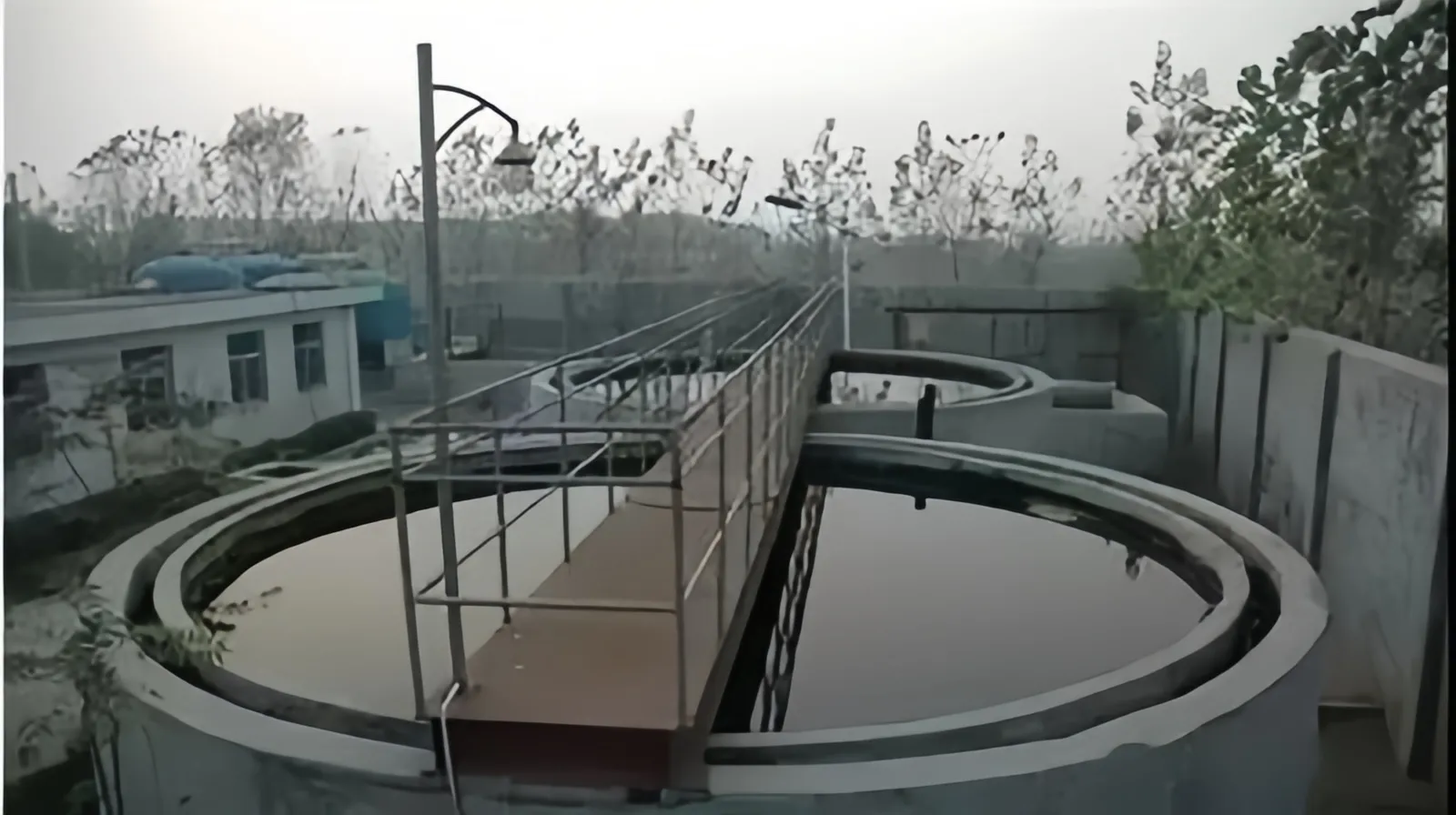
In radial flow tanks, water flows radially from the center or periphery.
Center Inlet: Wastewater enters through a centrally suspended or embedded pipe, passes through straightening vanes, then flows radially outward. Clarified water exits via peripheral weirs. Sludge settles to the bottom and is scraped to a central sludge hopper for discharge by gravity or pump.
Peripheral Inlet: Water enters via channels around the perimeter, flows inward or downward, and clarified water exits through central or peripheral weirs. Sludge removal is the same as for center-inlet tanks.
Basic Design Requirements:
a. Tank size: Diameter or side length to depth ratio = 6~12;Diameter: ≥ 16 m (can reach 100 m); bottom slope = 0.05~0.10
b. Sludge removal: Use mechanical scrapers with air-lift or gravity discharge
Tanks < 20 m in diameter may use four sludge hoppers
Sludge can be lifted by compressed air, pumps (submersible, screw), or discharged using static head
c. Inlet/Outlet Configurations: Center inlet, peripheral outlet;Peripheral inlet, center outlet;Peripheral inlet and outlet: Tanks < 20 m generally use center-driven scrapers
Tanks > 20 m use peripherally driven scrapers;
d. Scraper Speed: Rotation = 1~3 revolutions/hour,Outer scraper speed ≤ 3 m/min
e. Scum Control: Install scum baffles in front of weirs; scum is collected by scum blades on the scraper arm
f. Efficiency: Peripheral-inlet designs are more efficient, with surface loading up to twice that of center-inlet/peripheral-outlet designs
3. Inclined Plate (Tube) Sedimentation Tank
This type is based on the “shallow-depth sedimentation” principle, using inclined plates or honeycomb tubes to improve efficiency. Depending on the direction of water and sludge flow, there are counter-current, co-current, and cross-flow designs. In wastewater treatment, counter-current upflow designs are most common.
They are suitable for primary clarifiers and small-scale pre-treatment (e.g., oil separation). They are rarely used for secondary clarifiers because: Mixed liquor has high solids content and poor shock resistance.High DO can promote algae and biofilm growth on plates/tubes, reducing effectiveness and increasing clogging risk.
Because of their high surface loading rates (roughly double that of conventional clarifiers), inclined plate/tube tanks are ideal for retrofitting or space-constrained applications.
Basic Design Requirements:
a. Spacing:
Plate spacing = 80~120 cm;
Tube diameter = 50~80 mm
Plate/tube length = 1.0~1.2 m; inclination = 60°
b. Depth:
Water above and buffer below the plates/tubes = 0.5~1.0 m
c. Installation:
Plates should slope toward inlet;Baffles must be installed at side gaps to prevent short-circuiting;Use flow distribution systems like perforated or slotted plates; velocity through holes < 0.15 m/s
d. Outlet System:
Usually consists of multiple surface collection troughs
Collection methods: orifice-type or V-notch weirs
e. Sludge Removal:
Collected in hoppers and removed by gravity
Sludge should be discharged 1~2 times per day, or more frequently if needed
f. Hydraulic Retention Time (HRT): Primary clarifiers: ≤ 30 minutes;Secondary clarifiers: ≤ 60 minutes.
g. Cleaning System:
Must include plate/tube washing facilities
Use high-pressure water during maintenance or shutdowns to prevent clogging
h. Hydraulic Performance:
Surface loading = 3~6 m³/(m²·h), roughly twice that of conventional clarifiers
HRT = 30~60 minutes
Common types of secondary clarifiers include horizontal flow, radial flow, and inclined plate/tube sedimentation tanks.
1. Horizontal Flow Sedimentation Tank
Horizontal flow tanks are typically rectangular. Water enters through an inlet zone where flow is dissipated and equalized, then moves slowly in a horizontal direction through the sedimentation zone. Suspended solids settle to the bottom, while clarified water exits over weirs and is discharged through an outlet channel.
Basic Design Requirements:
Length: typically 30~50 m (not exceeding 60 m)
Width: typically 5~10 m
Effective depth: generally 2.5~3.0 m (not exceeding 3 m)
Length-to-width ratio ≥ 4: 1; length-to-depth ratio between 8~12
a. Sludge Collection: When mechanical sludge scrapers are used, sludge hoppers are installed at the inlet end. Tank bottom slope towards the sludge hopper should be ≥ 0.01 (usually 0.01~0.02). Scraper travel speed should not exceed 1.2 m/min (typically 0.3~0.9 m/min).
b. Hydraulic Loading: As a primary clarifier: surface loading rate = 1~4.5 m³/(m²·h), max horizontal velocity = 7 mm/s
As a secondary clarifier: surface loading rate ≤ 1 m³/(m²·h), max horizontal velocity = 5 mm/s.
c. Inlet Design: Must include flow-straightening devices. Common configurations include: Overflow weir + perforated baffle;Bottom inlet + baffle;Submerged inlet + baffle;Submerged inlet + perforated baffle.For perforated baffles: open area 6%~20% of cross-section; velocity through holes = 0.08~0.1 m/s; openings should be tapered.
d. Sludge Removal: Small tanks may use perforated pipes for sludge collection, placed in sludge hoppers or on the tank floor. Multi-hopper layouts should not exceed two rows. Large tanks typically use mechanical scrapers that move sludge to inlet-end hoppers and skim scum toward outlet-end scum troughs or pipes.
e. Buffer Zone: For non-mechanical sludge removal: buffer height = 0.5 m
For mechanical removal: buffer zone should extend 0.3 m above the scraper blade
2. Radial Flow Sedimentation Tank
In radial flow tanks, water flows radially from the center or periphery.
Center Inlet: Wastewater enters through a centrally suspended or embedded pipe, passes through straightening vanes, then flows radially outward. Clarified water exits via peripheral weirs. Sludge settles to the bottom and is scraped to a central sludge hopper for discharge by gravity or pump.
Peripheral Inlet: Water enters via channels around the perimeter, flows inward or downward, and clarified water exits through central or peripheral weirs. Sludge removal is the same as for center-inlet tanks.
Basic Design Requirements:
a. Tank size: Diameter or side length to depth ratio = 6~12;Diameter: ≥ 16 m (can reach 100 m); bottom slope = 0.05~0.10
b. Sludge removal: Use mechanical scrapers with air-lift or gravity discharge
Tanks < 20 m in diameter may use four sludge hoppers
Sludge can be lifted by compressed air, pumps (submersible, screw), or discharged using static head
c. Inlet/Outlet Configurations: Center inlet, peripheral outlet;Peripheral inlet, center outlet;Peripheral inlet and outlet: Tanks < 20 m generally use center-driven scrapers
Tanks > 20 m use peripherally driven scrapers;
d. Scraper Speed: Rotation = 1~3 revolutions/hour,Outer scraper speed ≤ 3 m/min
e. Scum Control: Install scum baffles in front of weirs; scum is collected by scum blades on the scraper arm
f. Efficiency: Peripheral-inlet designs are more efficient, with surface loading up to twice that of center-inlet/peripheral-outlet designs
3. Inclined Plate (Tube) Sedimentation Tank
This type is based on the “shallow-depth sedimentation” principle, using inclined plates or honeycomb tubes to improve efficiency. Depending on the direction of water and sludge flow, there are counter-current, co-current, and cross-flow designs. In wastewater treatment, counter-current upflow designs are most common.
They are suitable for primary clarifiers and small-scale pre-treatment (e.g., oil separation). They are rarely used for secondary clarifiers because: Mixed liquor has high solids content and poor shock resistance.High DO can promote algae and biofilm growth on plates/tubes, reducing effectiveness and increasing clogging risk.
Because of their high surface loading rates (roughly double that of conventional clarifiers), inclined plate/tube tanks are ideal for retrofitting or space-constrained applications.
Basic Design Requirements:
a. Spacing:
Plate spacing = 80~120 cm;
Tube diameter = 50~80 mm
Plate/tube length = 1.0~1.2 m; inclination = 60°
b. Depth:
Water above and buffer below the plates/tubes = 0.5~1.0 m
c. Installation:
Plates should slope toward inlet;Baffles must be installed at side gaps to prevent short-circuiting;Use flow distribution systems like perforated or slotted plates; velocity through holes < 0.15 m/s
d. Outlet System:
Usually consists of multiple surface collection troughs
Collection methods: orifice-type or V-notch weirs
e. Sludge Removal:
Collected in hoppers and removed by gravity
Sludge should be discharged 1~2 times per day, or more frequently if needed
f. Hydraulic Retention Time (HRT): Primary clarifiers: ≤ 30 minutes;Secondary clarifiers: ≤ 60 minutes.
g. Cleaning System:
Must include plate/tube washing facilities
Use high-pressure water during maintenance or shutdowns to prevent clogging
h. Hydraulic Performance:
Surface loading = 3~6 m³/(m²·h), roughly twice that of conventional clarifiers
HRT = 30~60 minutes